Security policy
(edit with the Customer Reassurance module)
 Delivery policy
(edit with the Customer Reassurance module)
 Return policy
(edit with the Customer Reassurance module)
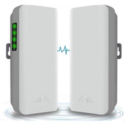
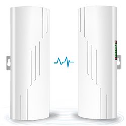
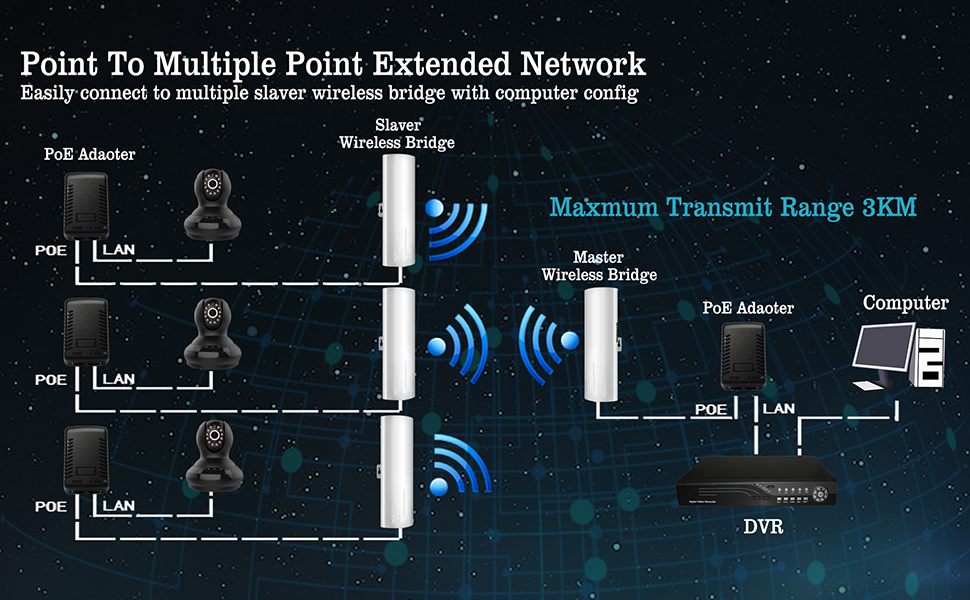
The CPE450 kit is one pair of outdoor high power and high performance 100Mbps wireless bridges, which works at 5GHz frequency. Supports Point-to-Point and Point-to-Multipoint wireless connection. It is more stable and of higher speed and anti-interference performance than 2.4GHz wireless bridges. Moreover, it is easy to manage through the WEB interface.
CPE450 Kit Function:
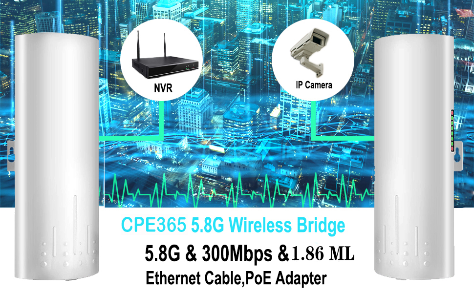
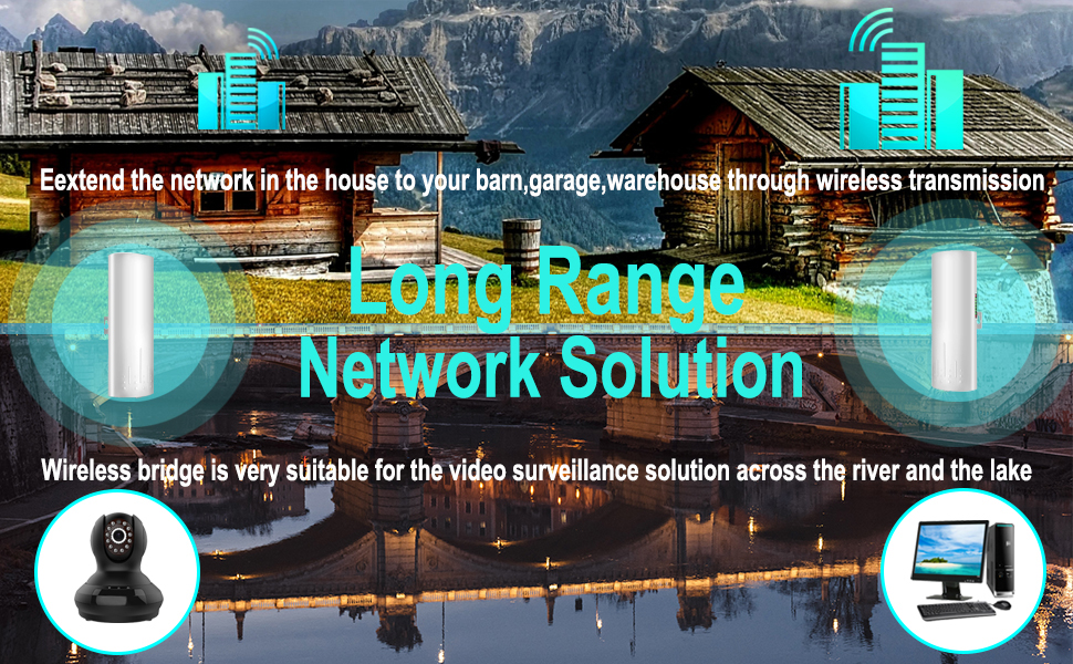
CPE450 Kit Application:
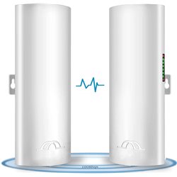
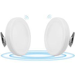
The master bridge and slave bridge must be installed face to face, the antenna is not omnidirectional, it has a 60 degrees transmission angle, the straight installation without blocking objects will lead to the best performance.
Wireless Bridge Master & Slave Set:
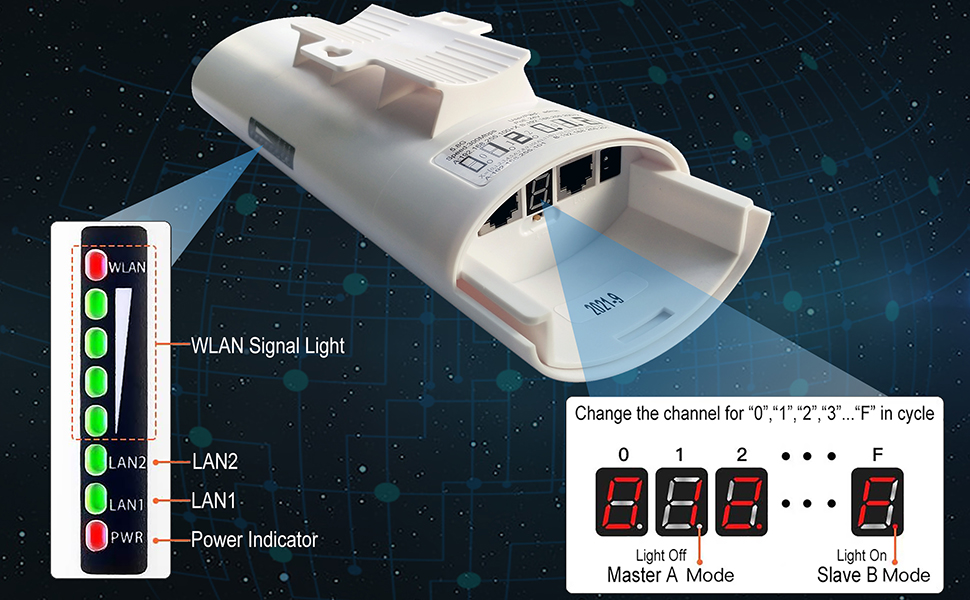
1.Master Bridge Setting
Move the mode switch to "A" position, the device works as master bridge.
2.Slave Bridge Setting
Move the mode switch to "B" position, the device works as slave bridge.
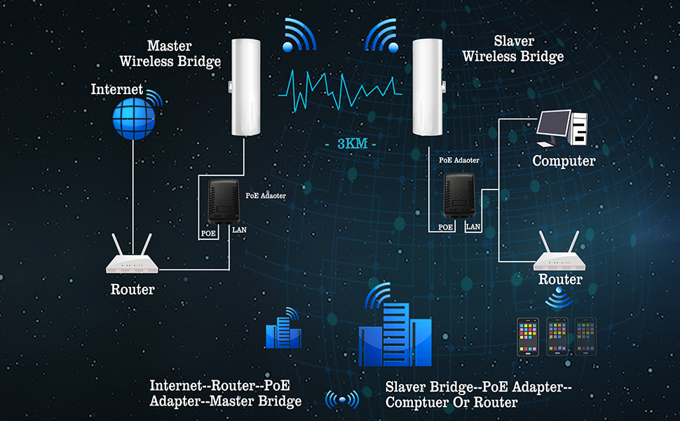
Wireless Bridge Connection
1.Bridge A Connection - Master Bridge
Step 1: The LAN port of the PoE Adapter connects to the router through an ethernet cable.
Step 2: The PoE port of the PoE adapter connects to the LAN port of the master wireless bridge by another ethernet cable.
2.Bridge B Connection - Slave Bridge
Step 1: The PoE port of the PoE adapter connects to the LAN port of slave bridge through an ethernet cable.
Step 2: The LAN port of the PoE adapter connects to the LAN port of the computer or router by another ethernet cable.
The master bridge and slave bridge must be installed face to face, the antenna is not omnidirectional, it has a 60 degrees transmission angle, the straight installation without blocking objects will lead to the best performance.
Wireless Bridge Master & Slave Set:
1.Master Bridge Setting
Move the mode switch to "A" position, the device works as master bridge.
2.Slave Bridge Setting
Move the mode switch to "B" position, the device works as slave bridge.
Wireless Bridge Connection
1.Bridge A Connection - Master Bridge
Step 1: The LAN port of the PoE Adapter connects to the DVR through an ethernet cable.
Step 2: The PoE port of the PoE adapter connects to the LAN port of the master wireless bridge by another ethernet cable.
2.Bridge B Connection - Slave Bridge
Step 1: The PoE port of the PoE adapter connects to the LAN port of the slave bridge through an ethernet cable.
Step 2: The LAN port of the PoE adapter connects to the LAN port of the switch by another ethernet cable.
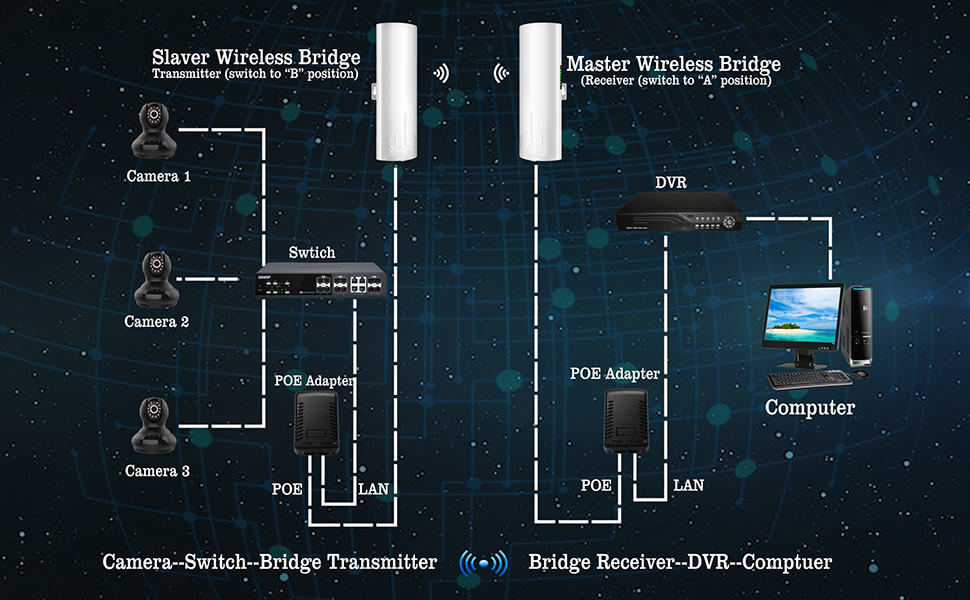
The master bridge and slave bridge must be installed face to face, the antenna is not omnidirectional, it has a 60 degrees transmission angle, the straight installation without blocking objects will lead to the best performance.
Wireless Bridge Master & Slave Set:
1.Master Bridge Setting
Move the mode switch to "A" position, the device works as master bridge.
2.Slave Bridge Setting
Move the mode switch to "B" position, the device works as slave bridge.
Wireless Bridge Connection
1.Bridge A Connection - Master Bridge
Step 1: The LAN port of the PoE Adapter connects to the DVR through an ethernet cable.
Step 2: The PoE port of the PoE adapter connects to the LAN port of the master bridge by another ethernet cable.
2.Bridge B Connection - Slave Bridge
Step 1: The PoE port of the PoE adapter connects to the LAN port of the slave bridge through an ethernet cable.
Step 2: The LAN port of the PoE adapter connects to the LAN port of the IP cameras by another ethernet cable.
The wireless bridges work by two modes, auto pairing mode with pre-programmed suits for newbie and customize mode suits for experienced user.
Auto pairing mode:
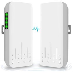
Connect the bridges to the PoE power adapter, the Power LED lamp turns green, system is power on, when both bridges are power on, they will auto pair in a few minutes, during the pairing the LAN status LED lamps all turn green. The digital LED indicator displays the numeric in red color.
You can find a good frequency without interference by pressing the "RST" button to change the channel, short press the button, the LED indicator will display the numeric "0","1","2","3"..."F" one by one, and change in cycle, each numeric means a different frequency, you can find the details in the user manual.
At the auto pairing mode, the bridge also output WiFi hot point, and the access password is pre-programmed in auto paring mode. When the channel changes, the access password changes as well. For example: the WiFi hot point name is CPE5G_5G161, and the default password is zllinkcpe123456161, if the name is CPE5G_5G153, the password will be zllinkcpe123456153. The last three numbers of the password must match the last three numbers of the name.
Customize mode:
At this mode the bridges must be connected to the computer and set different IP addresses and working modes, short press the "RST" button will not be functional at this mode, but you can press and hold this button for over 10 seconds to reset to factory setting.
|
Model: |
CPE450 |
|
Network Interface: |
10/100Mbps 2 * LAN Port |
|
Data Rate: |
11a: 54M, 48M, 36M, 24M, 18M, 12M, 9M, 6Mbps / 11n: 7.2M, 14.4M, 21.7M, 28.9M, 43.3M, 57.8M, 65M, 72.2M, 14.4M, 28.9M, 43.3M, 57.8M, 86.7M, 115.6M, 130M, 144.4Mbps |
|
Power Supply: |
POE 24V 1.0A |
|
Antenna: |
14DBi (5180~5825MHz) |
|
Transmittion |
3KM / 1.86 Miles |
|
Waterproof: |
IP65 |
|
Dust-proof: |
Support |
|
Working temperature: |
-4℉~158℉ |
|
Dimensions: |
250mm * 90mm * 65mm / 9.8'' * 3.55'' |
|
Weight: |
1.1kg / 38.8 oz (A pair) |